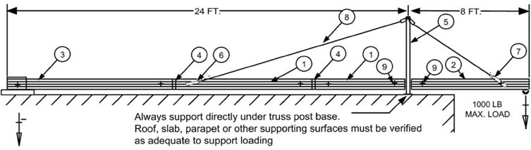
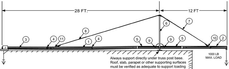
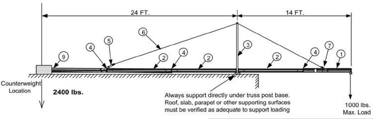
– Counterweight or clamp to structure to provide resistance to overturning with a safety factor of 4 to 1.
– Use counterweight saddles or long horn bar to secure additional weights as required (1400 LB weight required).
Tie back in accordance with applicable regulations and safe work practices